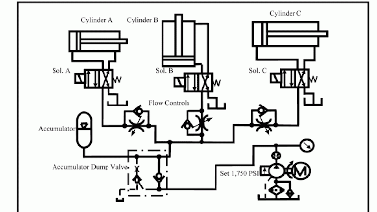
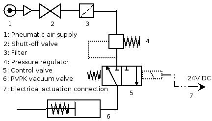
Pneumatic Actuation System Layout

Hydraulic Symbols Pneumatic Symbol Library Schematic Design Hydraulic Systems Engineering Symbols
Simplified Pneumatic Actuator Design And Operation Engineers Edge Www Engineersedge Com

How To Read Pneumatic Circuit Diagram Circuit And With Images Circuit Diagram Circuit Hydraulic Systems

Draw General Layout Of Pneumatic System And State Function Of Each Component In It
Chapter 5 Pneumatic And Hydraulic Systems Hydraulics Pneumatics

General Layout Hydraulic Pneumatic System
They are economical and utilize compressed air readily available in most plants.
Pneumatic actuation system layout.

Image Result For Log Splitter Design Plans Log Splitter Wood Splitter Splitters

Plumbing System Controls Valves Valve Plumbing Valves Plumbing
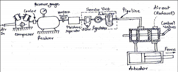
Draw A General Layout Of Pneumatic System And State The Function Of Components Topicwise Paper Solutions For Msbte

Nordyne Air Handler Wiring Diagram Fan Circuit Free For Ac Model E2eb 015ha 2 With E2eb 015ha Wiring Diagram Carrier Furnace Electric Furnace Thermostat Wiring

Small Below Grade Ground Run With Installing Basement Toilet Plumbing Diagrams For Closet And Bathroom

Plumbing Diagram For Pool System Curve In Pool Pump System Plumbing Diagrams On Head And Flow Pool Pump System Plumbing Diagrams

Branch Vent A Vent Connecting One Or More Individual Vents To A Stack Vent Building Systems Study Time Vented

This Model Uses Scenes Do Not Download Into Another Model Open As A New File This Sliding Blast Gate Is Pneu Dust Collection Mechanical Projects Duct Work

For Pneumatic Control System Components Choose Dasservicesinc A Broad Range Of Pneumatic Tools Like Vacuu In 2020 Rose Crafts Diy Aquarium Aquarium Fish Tank

Pin By Carlos Senosiain On That S A Fact In 2020 Blacksmith Power Hammer Power Hammer Power Hammer Plans

Engine Diagram On Peugeot 8 V8 Di 2020

Palma Air Defense Missile Gun And Gun System Kaskus The Largest Indonesian Community Weapon Guns Weapons Aircraft

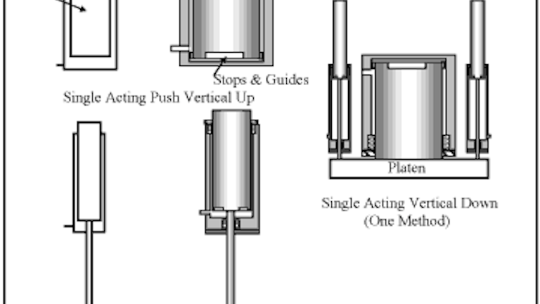
Single Acting Pneumatic Actuator Manufacturer Suppliers In The Globe In 2020 Control Valves Actuator Chemical Industry

Marathon Electric Motors Wiring Diagram Here Is An Example Of A Circuit That You Can Make The Guidelines For Making Jpg Wire Thermal Protectant Electric Motor

Pin On Radwell Tv
Control Systems

Pin On Valves
Book 2 Chapter 8 Directional Control Valves Hydraulics Pneumatics
Https Encrypted Tbn0 Gstatic Com Images Q Tbn 3aand9gcq16qkbt87f9q Dncjuebdivkbnregqa5p Epbykukj1rosrxgy Usqp Cau

Elevator Safety System Electrical Knowhow Elevation Safety Safety Gear

Limit Switch For Pneumatic Actuator Actuator Control Valves Valve

Fmcw Radar Level Transmitter Working Principle Transmitter Levels Directions


Types Of Traps Plumbing Installation Plumbing Traps
Source : pinterest.com
